C1902
C1902产品介绍
产品简介
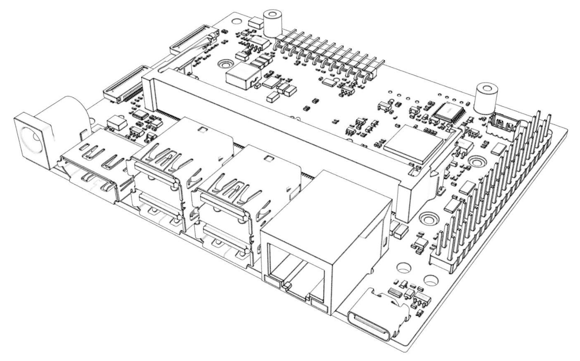
C1902 是一款针对 Jetson Orin Nano & NX 核心卡进行研发的载板,该底板基于公版方案进行开发,完美兼容官方设计套件的功能,包括全速的 USB3.0 接口及 TYPE-C 接口。
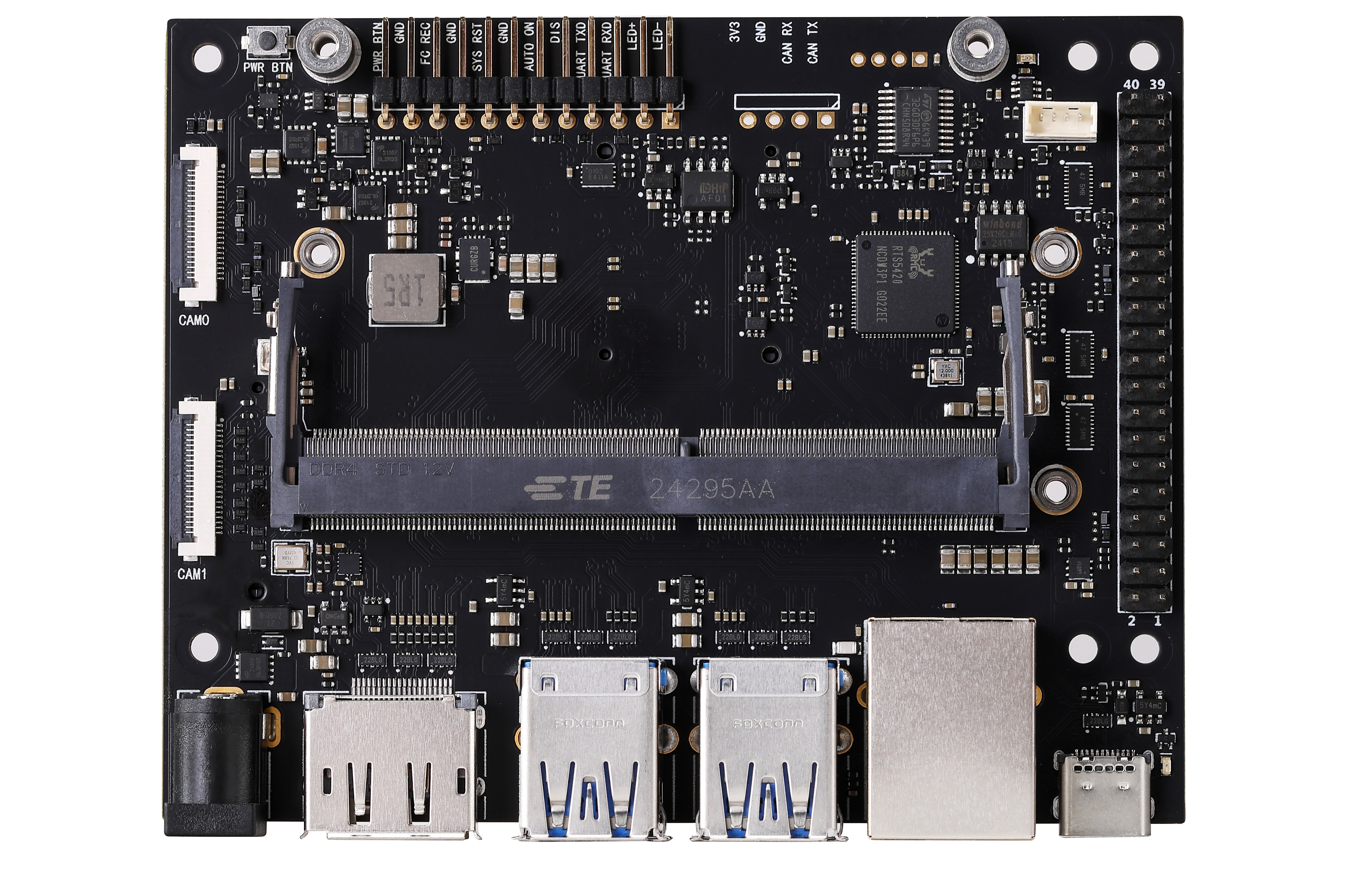
正面

背面
产品特点
- C1902 基于原厂方案进行开发,所有接口功能与原厂一致且可以 直接烧录 Developer Kit 固件。
- 支持 Orin Nano 4G/8G & Orin NX 8G/16G。
- 高品质 6 层沉金 PCB,全 MLCC 电容以及镀金连接器。
- 支持 NVME 硬盘 和 M.2 网卡。
版本迭代记录
| 版本 | 日期 | 备注 |
|---|---|---|
| V1.0 | 2024 Q3 | C1902 的第一个版本 |
| V1.1 | 2025 Q1 | 1. 修复了一个 GPIO 问题,该问题曾导致 12/35/38/40 号引脚在原厂设备树下不可用。 2. 增加了对 ORIN NANO/NX 全系列的 SUPER 模式的支持。 |
| V1.1.1 | 2025 Q2 | 1. 修改 DC 电源输入座子规格,由 DC5521 变为 5525。 |
产品规格
| 供电电压 | 12V(兼容 9-19V) |
| 工作温度 | 0℃ ~ 45℃ |
| 支持的核心 | Orin Nano 4G/8G Orin NX 8G/16G |
| 电源接口 | DC5525 |
| 以太网 | 1x 千兆网口(RJ45) |
| 无线网卡 | 1x M.2 Key E |
| 存储扩展 | 2x M.2 Key M (NVME SSD) |
| 显示 | 1x DP1.2 |
| USB | 4x USB3.2 (10Gbps) |
| USB C | 1x Type C (USB3.0) |
| 相机接口 | 2x CSI-2 22P |
| 其余接口 | 和原厂一致 |
| RTC 电池 | 支持 |
| POE 供电 | 不支持 |
- 本底板支持 12V (9V~19V) 供电,请保证电源拥有足够的功率,以保证系统工作正常。
- 当供电电压大于 15V 且负载较大时,请注意加强散热。
- 本产品支持电源输入反接保护,但原则上在任何时刻都不应反接电源。
- 每组 USB 接口合计最大输出电流为 2.5A,当系统监测到电流大于 2.5A 时,会切断 USB 供电输出。
- 背面网卡接口与 M.2 2230 接口相比原厂改为对称布局。
- 禁止在载板未断电时拔插核心卡,该行为会导致核心卡及载板损坏,由不规范操作产生的损失将由客户自行承担。
功能对比:
| 规格参数 | 原厂载板 | C1902(本产品) | C1901 |
|---|---|---|---|
| 供电电压 | 19V | 12V (兼容9-19V) | 12V (兼容9-19V) |
| 电源接口 | DC5525 | DC5525 | DC5521 (兼容DC5525插头) |
| 以太网 | 1x 千兆网口 (RJ45) | 1x 千兆网口 (RJ45) | 1x 千兆网口 (RJ45) |
| 无线网卡 | 1x M.2 Key E | 1x M.2 Key E | 1x M.2 Key E |
| 存储扩展 | 2x M.2 Key M | 2x M.2 Key M | 2x M.2 Key M |
| 显示接口 | 1x DP 1.2 | 1x DP 1.2 | 1x HDMI (1080P) |
| USB 接口 | 4x USB 3.0 | 4x USB 3.0 | 3x USB 3.0 + 1x USB 2.0 (需改设备树) |
| USB Type-C | 1x Type-C (USB 3.0) | 1x Type-C (USB 3.0) | 1x Type-C (USB 2.0) |
| 相机接口 | 2x CSI-2 2lane | 2x CSI-2 2lane | 2x CSI-2 2lane |
| RTC 电池 | 不支持 | 支持 | 支持 |
| POE 供电 | 支持 (但未焊接) | 不支持 | 不支持 |
| 其余接口 | - | 和原厂一致 | 和原厂一致 |
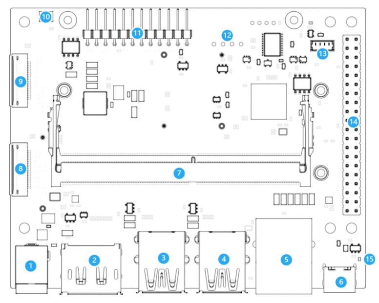
接口布局
| 序号 | 名称 | 备注 |
|---|---|---|
| 1 | 电源输入接口 | 接头规格:DC5525 |
| 2 | DP接口 | DP1.2输出接口 |
| 3 | USB Type-A 接口 | 2 x USB 3.0 |
| 4 | USB Type-A 接口 | 2 x USB 3.0 |
| 5 | 以太网接口 | 1000Mbps (千兆) 网口 |
| 6 | USB Type-C 接口 | 用于烧录固件 |
| 7 | 260-pin SO-DIMM 接口 | 连接Jetson核心卡 |
| 7 | 40Pin GPIO 接口 | 包含 (3x) I2C, (2x) SPI, UART, I2S, GPIOs |
| 8 | CSI0 接口 | 22P-CSI 接口 |
| 9 | CSI1 接口 | 22P-CSI 接口 |
| 10 | 启动按钮 | |
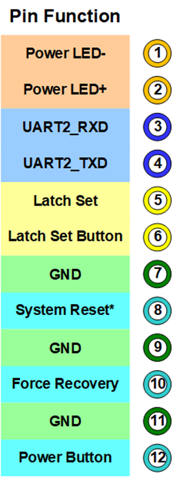
| 11 | 12-pin 调试接口 | |
| 12 | CAN 调试接口 | 未焊接 |
| 13 | 风扇接口 | 支持PWM调速 |
| 14 | 40pin拓展接口 | |
| 15 | Power LED |
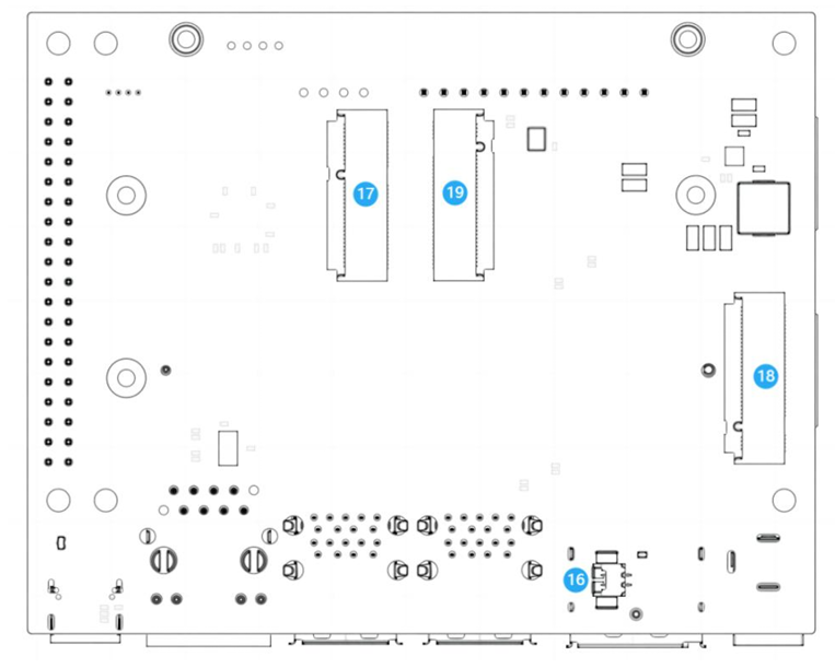
| 序号 | 名称 | 备注 |
|---|---|---|
| 16 | RTC 接口 | RTC时钟电池 |
| 17 | M.2 Key E | 2230规格 |
| 18 | M.2 Key M | 2280规格 |
| 19 | M.2 Key M | 2230规格 |
部分功能说明
- 启动按钮 (10):相比于原厂载板,C1902多设置了一个启动按钮,该按钮具有以下功能:
- 系统启动时:按动一次进入关机界面,长按 10 秒强制关机。
- 系统关闭时:按动一次进行开机。
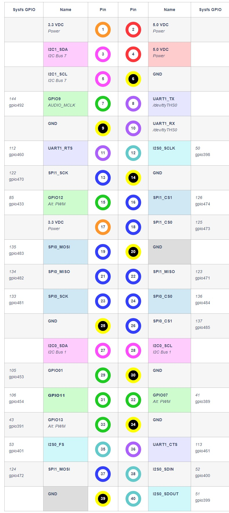
- 40PIN排针 (14):40Pin GPIO排针中的 5V 输出具有倒灌保护,该 5V 输出最大电流为 0.8A,过流会关断输出,参考定义如下(实际以核心卡为准)。
- 12Pin调试接口 (11) 定义如下:
- 固态硬盘必须使用单面版本,使用双面贴片版本固态硬盘,有可能发生干涉,引起短路。
- 电池接口 (4):相比于原厂载板,C1901 多设置了一个 RTC 电池连接器,该连接器型号为 MX1.25-2P,电池电压为 3V。使用电池时,请确认好极性,禁止接反电池。

接入电池后,需要进行配置才能启用 RTC 时钟,详情请参考 RTC 说明
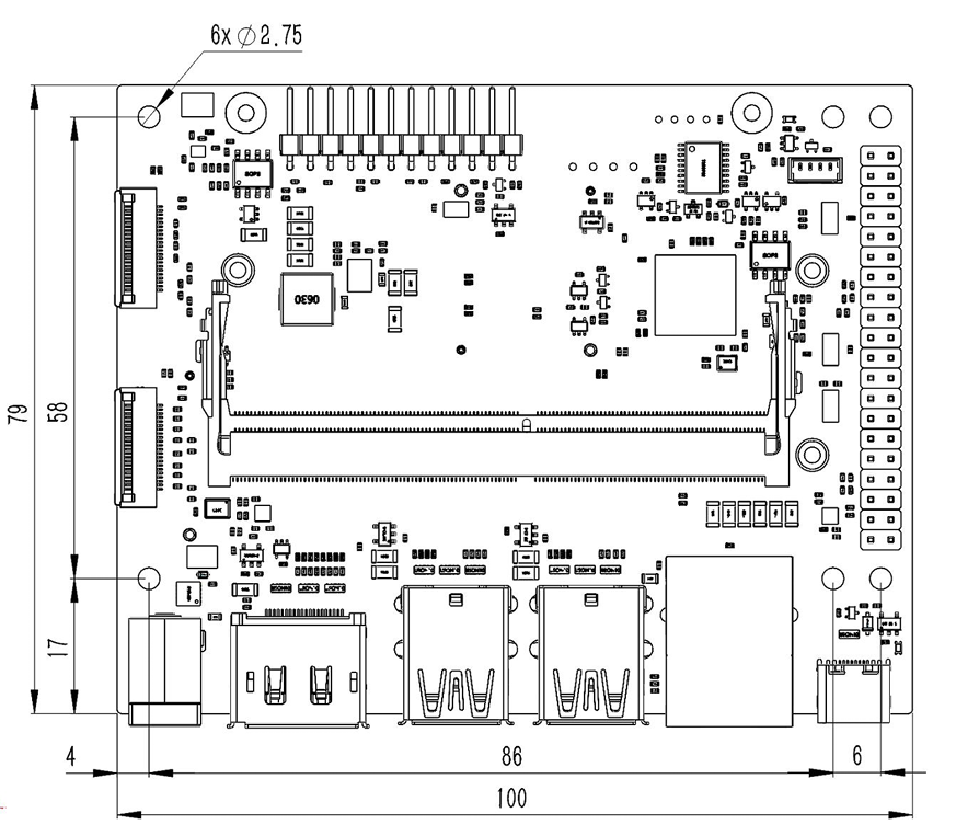
产品尺寸 (mm)
| 螺钉位置 | 推荐的规格 | 备注 |
|---|---|---|
| 载板固定孔 | M2.5 螺钉或铜柱 | 螺钉或铜柱直径不得大于 6mm |
| 核心卡、硬盘 | M2.5 x 4 薄头螺钉 | 推荐使用薄头螺钉,以避免干涉 |
| 网卡 | M2.5 x 4 薄头螺钉 | 推荐使用薄头螺钉,以避免干涉 |
技术支持
C1902 Introduction
Introduction
The C1902 is a development board specifically designed for Jetson Orin Nano & NX modules. Built on a standard board design, it fully supports the official developer kit's features, including full-speed USB3.0 and Type-C ports.

正面
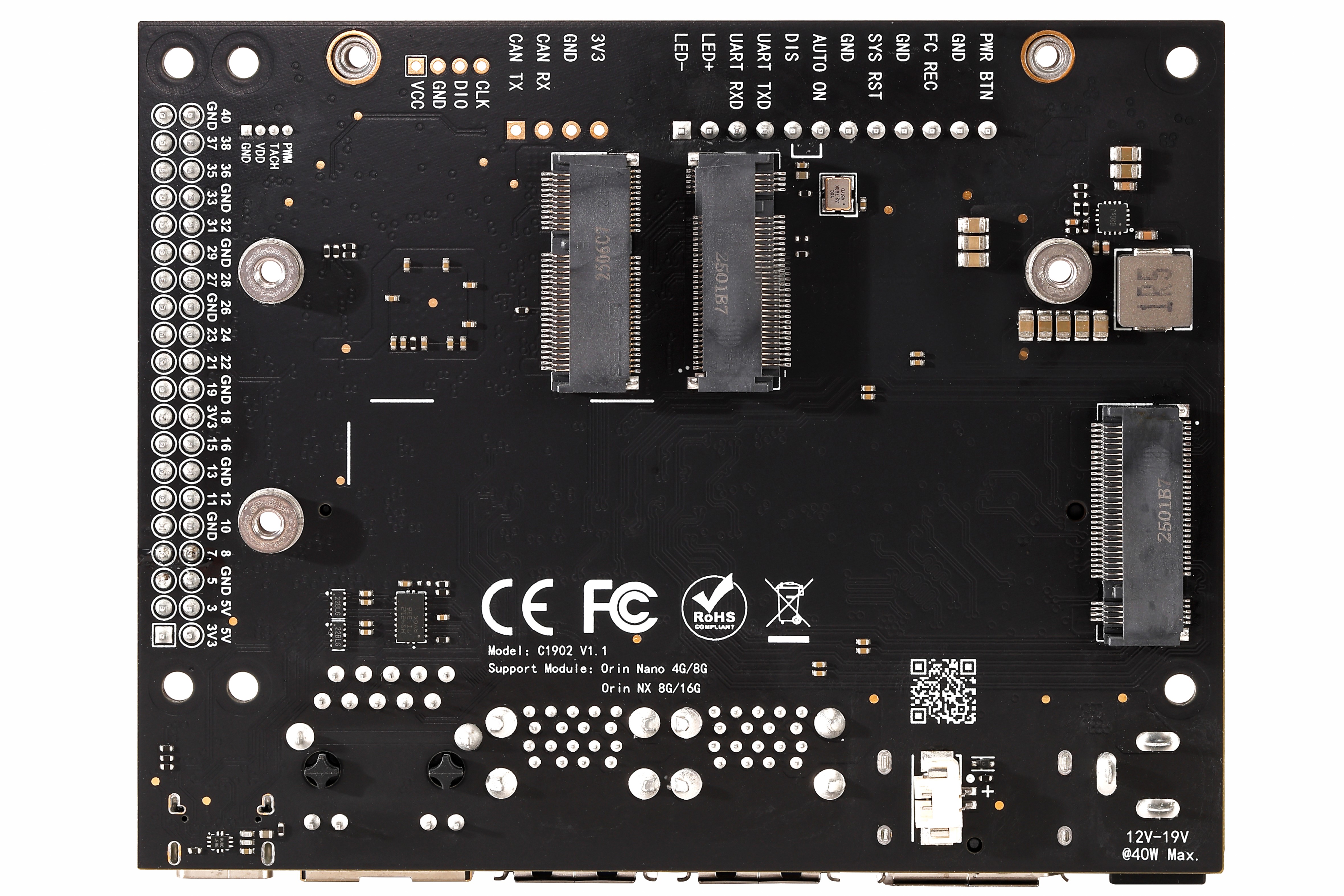
背面
Fearture
-
C1902 was developed based on the original manufacturer's solution, with all interface functions matching the original manufacturer's and supporting direct firmware flashing via Developer Kit
-
Compatible with NVIDIA® Jetson Orin Nano (4GB/8GB) and Orin NX (8GB/16GB) modules.
-
Premium 6-layer gold-plated PCB with full MLCC capacitors and gold-plated connectors
-
Supports M.2 NVMe SSD and M.2 Wi-Fi module
History
|
Version |
Date |
Description |
|
V1.0 |
2024 Q3 |
The first version of C1902 |
|
V1.1 |
2025 Q1 |
1. Fixed a GPIO issue that previously caused pins 12/35/38/40 to be unavailable under the original device tree. 2. Enhanced support for the SUPER mode across the entire ORIN NANO/NX series |
|
V1.1.1 |
2025 Q2 |
3. Modify the DC power input socket specifications from DC5521 to DC5525 |
Datasheet
|
Supply Voltage |
12V (compatible with 9-19V) |
|
Operating Temperature |
0℃~45℃ |
|
Supported Module |
Orin Nano 4G/8G Orin NX 8G/16G |
|
Power Connector |
DC5525 |
|
Ethernet |
1x Gigabit Ethernet Socket (RJ45) |
|
Wireless Network Adapter |
1x M.2 Key E |
|
External Storage |
2x M.2 Key M (NVME SSD) |
|
DisplayPort |
1x DP V1.2 |
|
USB |
4x USB3.2 (10Gbps) |
|
USB C |
1x Type C (USB3.0) |
|
Camera |
2x CSI-22P |
|
Other |
Consistent with original specs |
|
RTC |
support |
|
POE |
not supported |
-
The carrier board requires a 12V(compatible with 9-19V) DC power supply. To ensure normal system operation, a power adapter with sufficient current output must be used. Additionally, under high load conditions with an input voltage exceeding 15V, adequate heat dissipation must be provided to prevent overheating.
-
This product includes reverse-polarity protection. Nevertheless, do not connect the power supply in reverse.
- The over-current protection (OCP) threshold for all USB ports is 2.5A. Exceeding this limit will trigger an automatic shutdown of the power output.
- In contrast to the original M.2 2230 interface, the backplane's network interface now features a symmetrical layout.
-
Do not hot-swap the module. Always power off the board before inserting or removing the module. Failure to do so may damage the module and the carrier board. Damage caused by improper operation is not covered under warranty.
Camparison:
|
|
Original |
C1901 V1.3 |
C1902 V1.1 |
|
Supply Voltage |
19V |
12V (compatible with 9-19V) |
12V (compatible with 9-19V) |
|
Power Connector |
DC5525 |
DC5521 (compatible with DC5525) |
DC5525 |
|
Ethernet |
1x Gigabit Ethernet Socket (RJ45) |
1x Gigabit Ethernet Socket (RJ45) |
1x Gigabit Ethernet Socket (RJ45) |
|
Wireless Network Adapter |
1x M.2 Key E |
1x M.2 Key E |
1x M.2 Key E |
|
External Storage |
2x M.2 Key M |
2x M.2 Key M |
2x M.2 Key M |
|
Display |
1x DP V1.2 |
1x HDMI (1080P) |
1x DP V1.2 |
|
USB |
4x USB3.0 |
3x USB3.0+1 xUSB2.0 (requires device tree modification) |
4x USB3.0 |
|
USB C |
1x Type C (USB3.0) |
1x Type C (USB2.0) |
1x Type C (USB3.0) |
|
Camera |
2x CSI-22P |
2x CSI-22P |
2x CSI-22P |
|
RTC |
Not Supported |
Supported |
Supported |
|
Other |
- |
Match the original |
Match the original |
|
POE |
Supported (Not Populated) |
Not Supported |
Not Supported |
|
SUPER Mode |
Only ORIN NANO series is supported |
Only ORIN NANO series is supported |
Supports the ORIN Nano/NX series |
Interface Layout
|
1 |
Power Jack |
9 |
Camera (#0) Connector (22p, 0.5 mm) |
|
2 |
DP Connector |
10 |
Power Button |
|
3 |
USB 3.0 Type A(x2 Stacked) |
11 |
Button Header (1x12, 2.54 mm) |
|
4 |
USB 3.0 Type A(x2 Stacked) |
12 |
CAN Bus Header (1x4, 2.54 mm) |
|
5 |
RJ45 Ethernet Socket |
13 |
Fan Header |
|
6 |
USB Type C |
14 |
40-pin Expansion Header(2x20, 2.54 mm) |
|
7 |
Jetson Orin Module Connector |
15 |
Power LED |
|
8 |
Camera (#1) Connector (22p, 0.5 mm) |
|
|
|
16 |
RTC Socket |
18 |
M.2 Key M Socket (4-lane) |
|
17 |
M.2 Key E Socket (75-pin) |
19 |
M.2 Key M Socket (2-lane) |
Feature Deatial
-
Power Button (10): The C1902 incorporates an additional function button not present on the reference board. Its operation is as follows:
System Running:A short press enters the shutdown menu; a long press (10 seconds) forces a power-off.When the system is off: press once to power on.
System Off: A short press powers on the system.
-
Expansion Header (14): The 40-pin GPIO header provides a 5V output rail with reverse current protection. It supports a maximum current of 0.8A and is safeguarded by over-current protection (OCP), which automatically disables the output upon detecting a fault. Actual performance depends on the specific system-on-module (SOM) in use. Please refer to the specifications below.
Reference link: https://jetsonhacks.com/pinouts/
- The 12Pin Header (11) is defined as follows:
-
The RTC battery port (16) on the C1902 board features an additional MX1.25-2P connector compared to the original factory board. When using RTC batteries, ensure correct polarity and avoid reverse connections.
After connecting the battery, configure the device to enable RTC clock. For details on RTC configuration and UART interface usage, please refer to RTC 说明
Mechanical Dimensions (mm)
|
Screw Location |
Recommended Specification |
Note |
|
Carrier Board Mounting Holes |
M2.5 screws or standoffs |
The diameter of the screw or standoff must not exceed 5mm. |
|
Module |
M2.5 × 4 pan head screws |
|
|
Hard Drive & Network Card |
M2.5 × 4 pan head screws |
Pan head screws are recommended. |