C2401 Inroduction
Introduction
The C2401 is a compact, high-density carrier board designed for NVIDIA Jetson Orin Nano/NX modules. It boasts comprehensive connectivity options, including dual Ethernet ports, dual USB ports, and expansion support for 4G/5G modules. Its space-saving stacked design ensures excellent ease of integration.
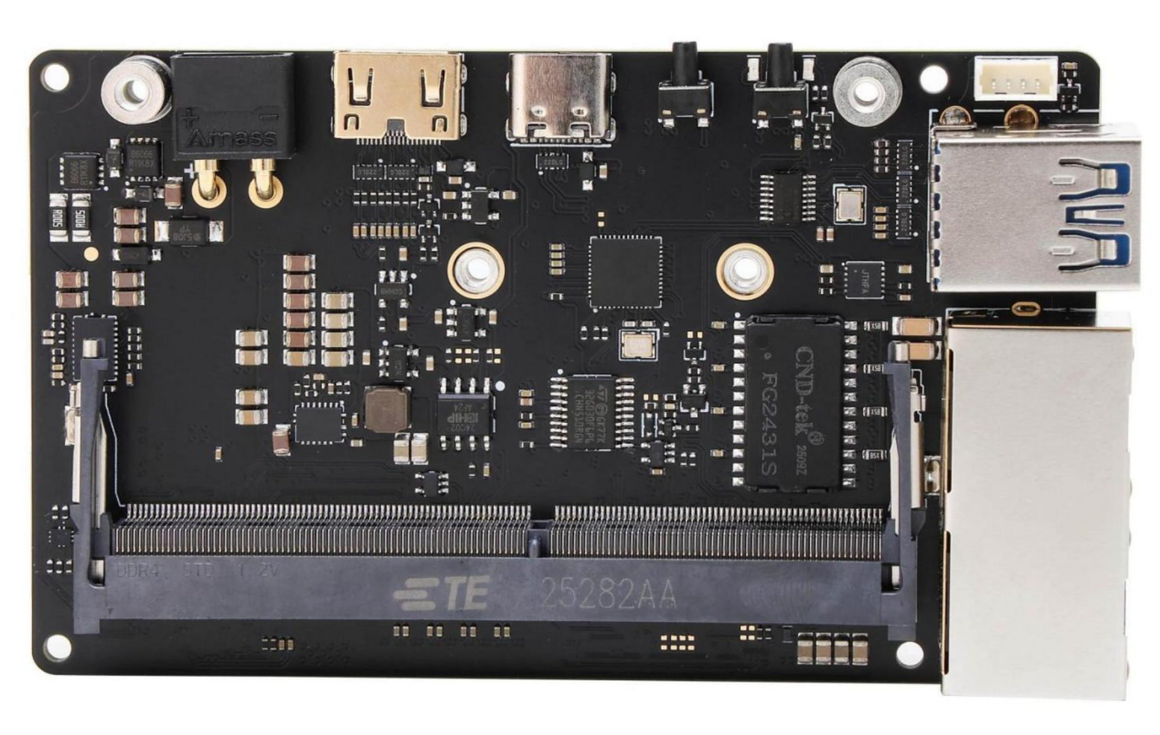
正面

背面
Features
- Equipped with an advanced automotive-grade E-fuse chip, providing comprehensive protection against over-voltage, under-voltage, short-circuit, over-current, and reverse polarity.
- Utilizes an ultra-low-resistance Buck chip, matched with an advanced alloy flat-wire inductor, featuring low heat generation and high saturation current characteristics to ensure stable power supply to the module.
- Features an 8-layer, 2u gold-plated, via-in-pad (VIP) process PCB, combined with a compact, high-density design, resulting in an external dimension of only 55x92mm.
- Rich peripheral interfaces, including dual USB 3.0 ports and dual network ports (Ethernet). One of the 2.5G ports supports the PTP (Precision Time Protocol) and high-density jumbo frames up to 16K bytes.
- The M.2 interface is designed on the same side for excellent accessibility and practicality. This allows for the replacement of the Wi-Fi card or solid-state drive (SSD) without needing to dismantle the module. It also includes a secondary development interface for expansion, such as 4G/5G network adapter.
产品规格
|
Supply Voltage |
12V (compatible with 9.5V-30V) |
|
Power Connector |
XT30 interface |
|
Supported Module |
Orin Nano 4G/8G Orin NX 8G/16G |
|
Ethernet |
1x Gigabit Ethernet Socket (RJ45) , supports 9KB jumbo frames 1x 2.5G Ethernet Socket (RJ45) , supports 16KB jumbo frames and PTP protocol |
|
Wireless Network |
1x M.2 Key E(2230) |
|
External Storage |
1x M.2 Key M (2230 NVME SSD) |
|
DisplayPort |
1x Mini HDMI V2.1 |
|
USB |
2x USB3.2 (10Gbps) 1xUSB2.0(GH1.25-4p) |
|
USB-C |
1x Type C (USB 2.0) for firmware flashing |
|
Camera |
1x CSI-22P |
|
Other |
UART, CAN, I2C |
|
RTC |
1x RTC backup clock battery interface |
|
Operating Temperature |
0℃~45℃ |
l The carrier board requires a 12V(compatible with 9.5-30V) DC power supply. To ensure normal system operation, a power adapter with sufficient current output must be used. Additionally, under high load conditions with an input voltage exceeding 15V, adequate heat dissipation must be provided to prevent overheating.
l This product includes reverse-polarity protection. Nevertheless, do not connect the power supply in reverse.
l The overcurrent protection (OCP) threshold for all USB ports is 2.5A. Exceeding this limit will trigger an automatic power-off.
l In contrast to the original M.2 2230 interface, the backplane's network interface now features a symmetrical layout.
Do not hot-swap the module. Always power off the board before inserting or removing the module. Failure to do so may damage the module and the carrier board. Damage caused by improper operation is not covered under warranty.
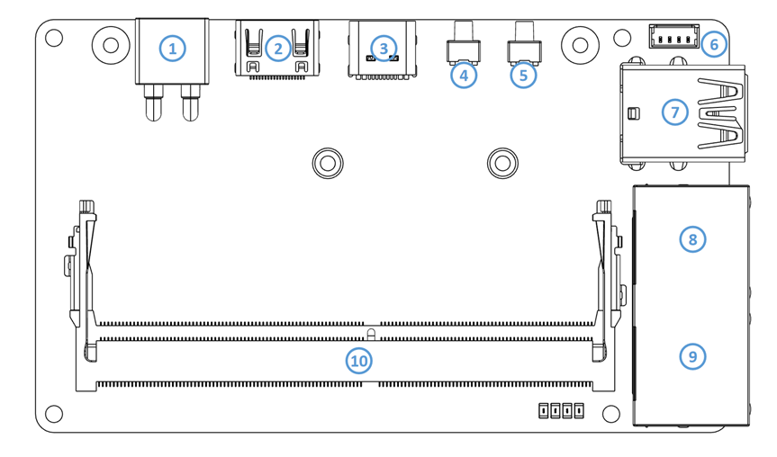
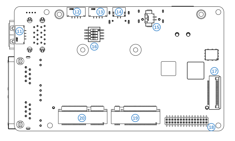
Interface Layout
| 序号 | 名称 | 序号 | 名称 |
|---|---|---|---|
| 1 | XT30 Power Jack | 11 | USB2.0 Connector (GH1.25 4p) |
| 2 | Mini HDMI | 12 | UART2 Connector (GH1.25 4p) |
| 3 | USB Type C (USB2.0) | 13 | UART1 Connector (GH1.25 4p) |
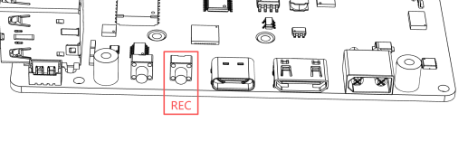
| 4 | REC Button | 14 | CAN Bus (GH1.25 2p) |
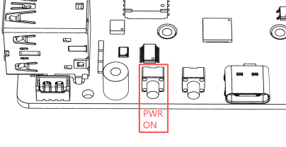
| 5 | Power Button | 15 | RTC |
| 6 | PWM Fan | 16 | 4Pin Switch |
| 7 | USB 3.0 Type A | 17 | Camera (#1) Connector 22pin 0.5mm |
| 8 | RJ45 1 (2.5G) | 18 | 30Pin Expansion Interface |
| 9 | RJ45 2 (1000M) | 19 | M.2 M-key (2230) |
| 10 | Jetson Orin Module Interface (SODIMM) | 20 | M.2 E-key (2230) |
Partial Features and Interfaces
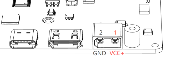
Power interface (1)
电源接口使用The power interface uses the XT30PW-M36 接口,与其配对的连接器型号是connector, paired with the XT30U-F,具体定义如下。F connector, as defined below.
推荐输入电压为The 该接口具有反接保护,但原则上任何时候都需检查好极性,确认正确再接入电源。the 当使用over-voltage protection(OVP) is 31V.
l 12V,可支持的电压范围是recommended input voltage is 12V, and the supported voltage range is 10V-30V。欠压保护电压为30V. The under-voltage protection(UVP) voltage is 9.5V,过压保护5V, 31V。and
l The interface has reverse protection, but always verify the power polarity before connecting the power supply.
l When using the ORIN NANO 系列时,请保证输入电源拥有最少series, 45Wensure 的输出能力,使用the input power supply has a minimum output capacity of 45W. For the ORIN NX 系列时,请保证输入电源拥有最少series, 60Wensure 的输出能力。the
Module |
Recommended power output |
USB-C |
|
ORIN NANO 4G/8G |
45W |
Minimum 20V 2.25A protocol |
|
ORIN NX 8G/16G |
60W |
Minimum 20V 3A |
REC 按钮Button (4)
The C2401 载板有两种方式进入恢复模式carrier board supports two methods for entering recovery mode:
方式一(按键法):在断电的情况下,按下When the power is off, press the REC
按钮不放,再接通电源,即可进入恢复模式,进行刷机等操作(请注意,恢复模式仅持续button and turn on the power to enter recovery mode for operations like flashing.(Note: Recovery mode lasts only 60
秒,系统检测到无刷机操作后,会自动进入正常开机时序。)seconds. The system will automatically resume normal startup after detecting no connection.)
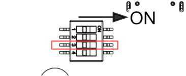
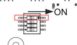
方式二(拨码法):将载板背面的拨码开关Set the DIP switch 3
拨动至onON,这样在每次上电时,系统都将会进入恢复模式。the back of the carrier board to ON, enabling the system to automatically enter recovery mode upon each power-on.
启动按钮
Power Button (5)
l The C2401 设置了一个启动按钮,该按钮具有以下功能:unit is equipped with a power button (5) that performs the following functions:
系统启动时:按动一次进入关机界面,长按When the system starts: Press once to enter the shutdown interface, and hold for 10秒强制关机。seconds 系统关闭时:按动一次进行开机。to
When the system is shutting down: press once to start up.
禁用自动开机:将载板背面的拨码开关Disable automatic startup: Set the DIP switch 2
拨动至onON,将禁用上电自动开机,需手动按动启动按钮进行开机。the back of the board to ON to disable automatic power-on. Manually press the power button to power on.

拓展排母
Expansion Header (18)
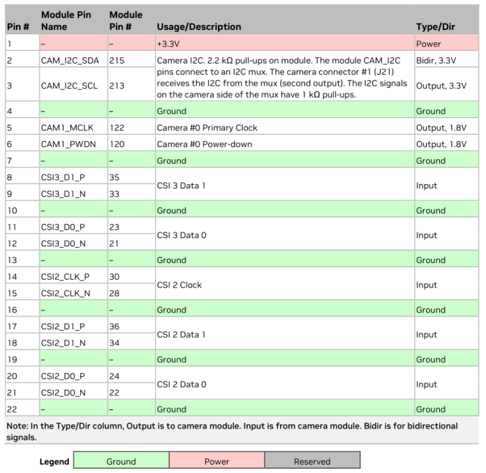
该排母规格为This 2x15Pis a 2x15-pin, 1.27mm,第一脚及定义如下:27mm pitch female header. Pin 1 location and pin definitions are as follows:
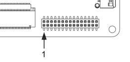
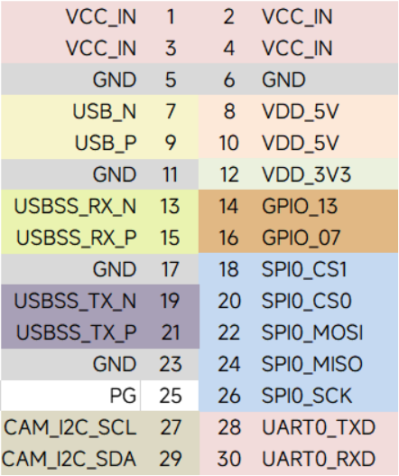
I2C、GPIO、SPI、l The I2C, GPIO, SPI, and UART
电平均为pins operate at 3.3V..l PG signal: Outputs a high level (Active High) when the module is operating normally.
l USB 3.
3V。0 PGports信号:当上层板正常工作时,输出高电平。13, 13、15、19、15, 19, and 21这组areUSB3.0disabled接口,在使用官方固件的情况下默认是关闭的,开启教程请参考by default in the official firmware. To enable them, please refer to the tutorial at:设备树替换说明。https://www.linkzeelabs.com/wiki/books/jetson-orin-nano/page/orin-nanonx-usb
l The VCC IN 的电压大小取决于输入电压,最大不能超过voltage 3A,matches the input voltage (Pass-through), with a max current of 3A. VDD_5V 和and VDD_3V3 最大能提供provide up to 1A 电流。each.
CSI 接口Interface (17)
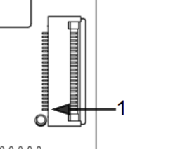
For the CSI 摄像头接口使用教程请参考:camera interface usage tutorial, please refer to: CSI 接口说明https://www.linkzeelabs.com/wiki/books/jetson-orin-nano/page/b534b
USB、串口及
USB, Serial Port, and CAN
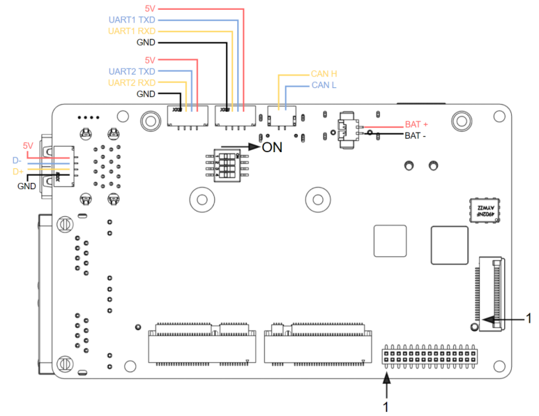
- RTC
电池接口battery port (15):: MX1.25-2P connector. When installing a battery, ensure correct polarity. Note:该连接器型号为SoftwareMX1.25-2P,使用电池时,请确认好极性,禁止接反电池。接入电池后,需要进行配置才能启用configuration is required to enable the RTC时钟。after installation.
l The CAN 接口interface (14):: 定义如上图所示,使用 GH1.25-2P 接口。CANconnector. 接口默认不接入终端电阻,可将载板背面的拨码开关Default state: No termination resistor. Set DIP switch 1 拨动至to ON,接入ON 120Ωto 终端电阻。具体配置方法请参考enable CAN配置说明the built-in 120Ω termination resistor.
-
UART (12) and (13)
:: GH1.25-4P connectors with 3.3V logic levels.使用的连接器型为UART2 is reserved for DEBUG mode. The 5V output supports a maximum current of 0.5A. -
The USB2.0 port (11): GH1.25-
4P,接口电平为4P3.3V,其中connector.UART2Supports只能用于aDEBUG,该接口maximum 5V输出最大电流为output current of 0.5A。5A.
USB 2.0 接口 (11):使用的连接器型号为 GH1.25-4P,该接口 5V 输出最大电流为 0.5A。
For details on RTC 时钟配置方法,及configuration and UART 等接口使用方法,请参考interface usage, please refer to RTC配置说明链接https://www.linkzeelabs.com/wiki/books/jetson-orin-nano/page/3c778
RJ45网口
- 千兆网口 (8): 使用与原厂一致的RTL8111千兆网卡芯片,无需额外调试驱动。
- 2.5G网口 (9): 使用RTL8125 2.5G网卡,启用需要额外安装驱动,具体说明参考有线网卡驱动设置。
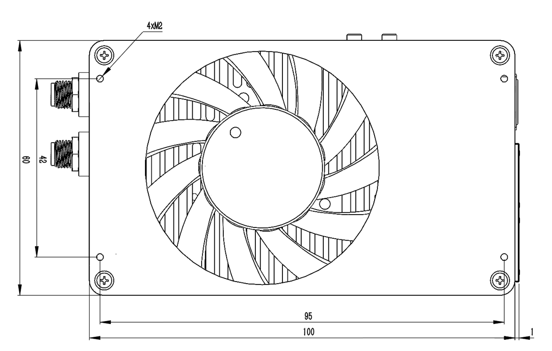
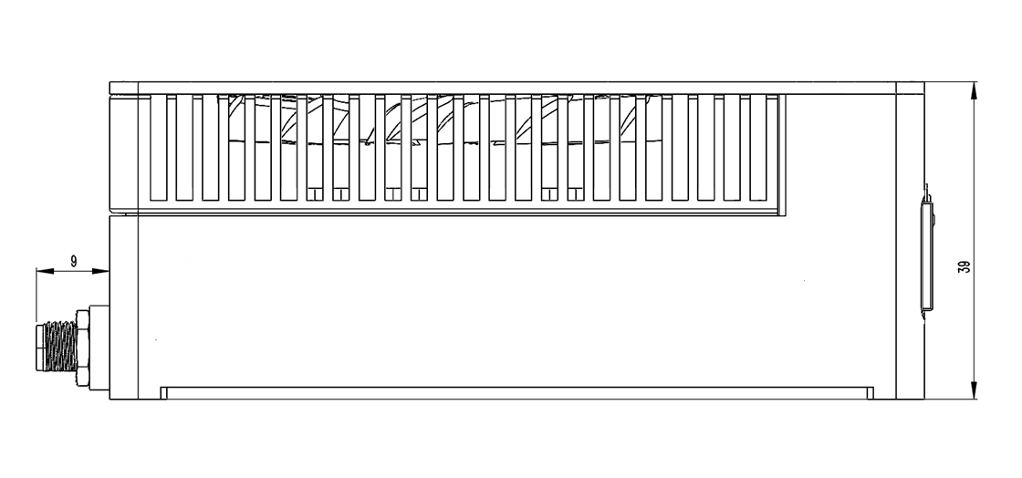
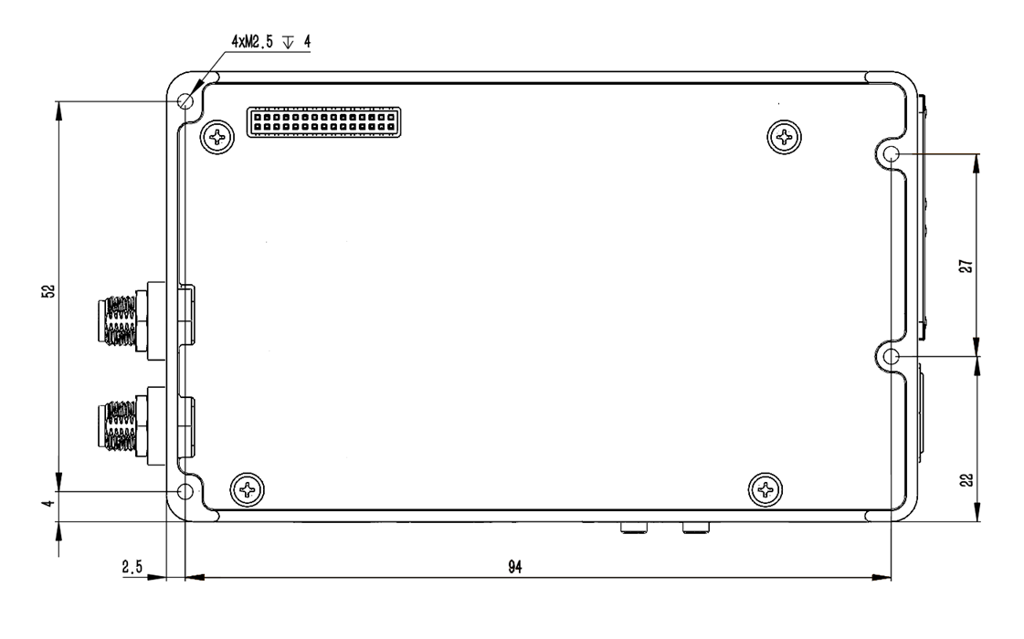
产品载板尺寸
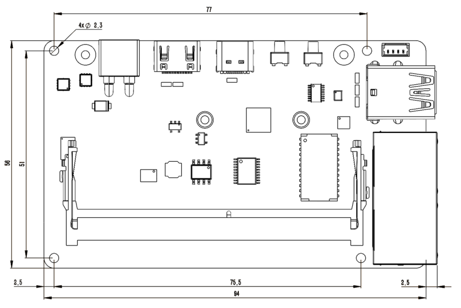
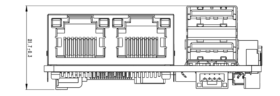
Mechanical Dimensions (Unit: mm)
|
Recommended Specification |
Note |
||||
Carrier Board Mounting Holes |
M2 |
The diameter of the screw or standoff must not exceed 4. |
|||
Module |
M2. |
The diameter of the screw or standoff must not exceed 5mm. |
|||
Hard Drive & Network Card |
M2. |
Pan head screws are recommended. |
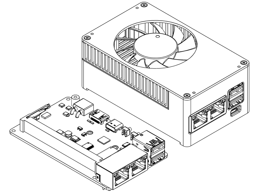
产品套件尺寸
Kit Dimensions (Unit: mm)