
Other Peripherals
1. UART Interface
1.1 Using UART with cutecom
cutecom is a cross-platform serial terminal program that provides a simple and intuitive graphical user interface, allowing users to send and receive data over a serial interface. Run the following command to install cutecom:
sudo apt install cutecom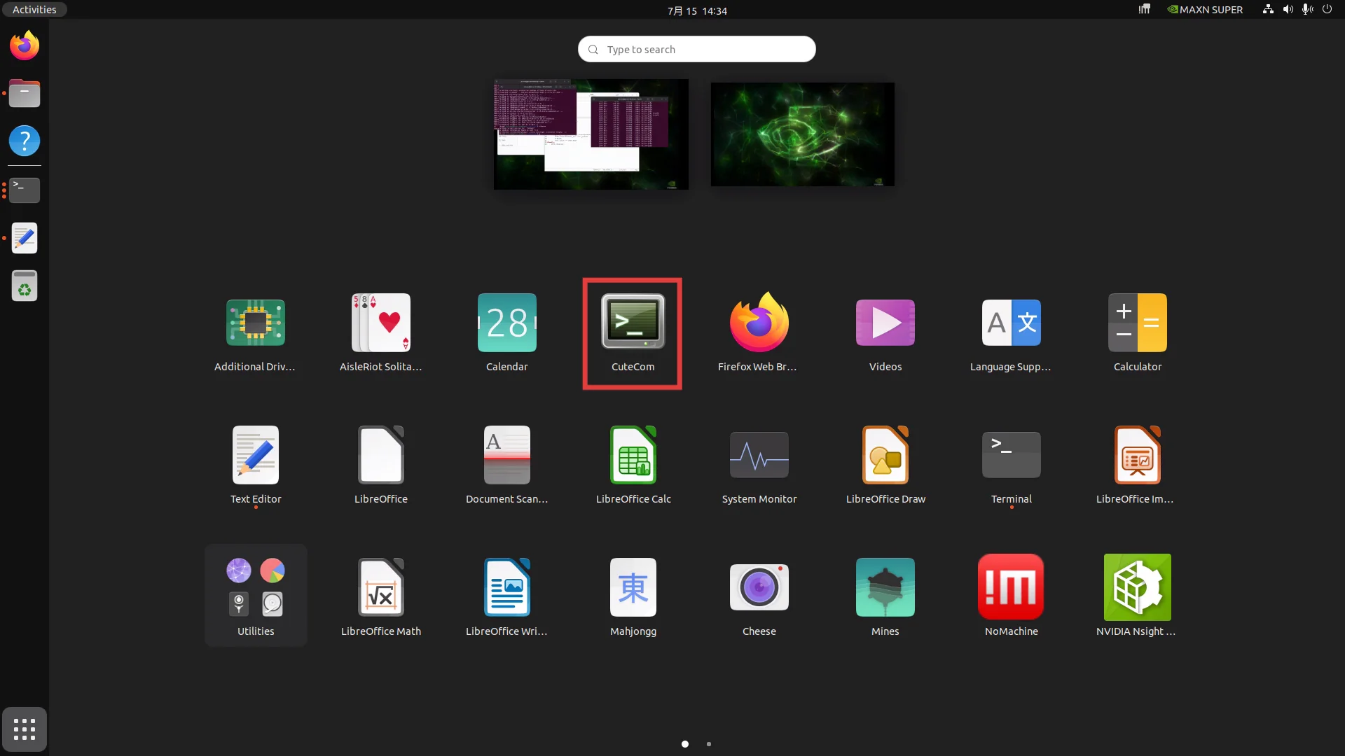
The UART interface enabled by default is ttyTHS1, which corresponds to pin 8 (TX) and pin 10 (RX) of the 40-pin GPIO header.
- Short pins 8 and 10 together with a jumper wire
- Change the serial port permissions (temporary authorization)
sudo chmod 777 /dev/ttyTHS1- Run the following command to add the current user to the user group. (Optional, permanent authorization)
sudo usermod -aG dialout $USER- Open cutecom, select ttyTHS1 and open it.
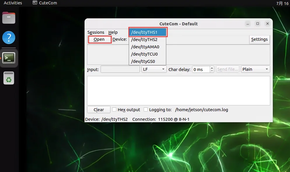
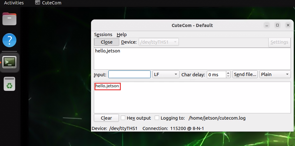
- Enter text and press Enter; you can see the content displayed in the receive area below.
1.2 Using UART with Python
- Change the serial port permissions
sudo chmod 777 /dev/ttyTHS1- Install the pyserial library
pip install pyserial- Run the following script to test
import serial
import time

PORT = "/dev/ttyTHS1"
BAUDRATE = 115200
ENCODING = "UTF-8"
MESSAGE = "hello,jetson\r\n"

try:
    with serial.Serial(PORT, BAUDRATE, timeout=2) as se:
        print(f"Serial port {PORT} opened: {se.is_open}")
        while True:
            se.write(MESSAGE.encode(ENCODING))
            print(f"Sent: {MESSAGE.strip()}")
            try:
                line = se.readline().decode(ENCODING).strip()
                if line:
                    print(f"Received: {line}")
            except Exception as e:
                print(f"Read error: {e}")
            time.sleep(1)
except serial.SerialException as e:
    print(f"Serial error: {e}")
except KeyboardInterrupt:
    print("\nExit by user.")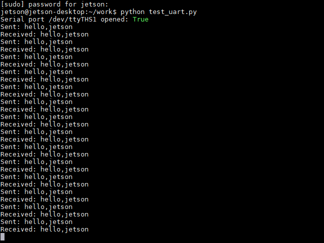
2. SPI Interface
- Check the SPI resources on the board
jetson@ubuntu:~/Downloads$ lsmod | grep -i spi
spidev                 28672  0
spi_tegra114           32768  0
2.1 SPI Communication with C/C++
Take SPI0 as an example; short pins 19 and 20 together with a jumper wire
- Download the SPI example
git clone https://github.com/rm-hull/spidev-test- Compile the source file
cd spidev-test
gcc spidev_test.c -o spidev_test- Run the example
sudo modprobe spidev  # load the official SPI driver
./spidev_test -D /dev/spidev0.0 -s 100000 -p "\x11\x22\x33" -v
The correct test result is as follows:
jetson@ubuntu:~/spidev-test$ ./spidev_test -D /dev/spidev0.0 -s 100000 -p "\x11\x22\x33" -v
spi mode: 0x0
bits per word: 8
max speed: 100000 Hz (100 KHz)
TX | 11 22 33 __ __ __ __ __ __ __ __ __ __ __ __ __ __ __ __ __ __ __ __ __ __ __ __ __ __ __ __ __  | ."3
RX | 11 22 33 __ __ __ __ __ __ __ __ __ __ __ __ __ __ __ __ __ __ __ __ __ __ __ __ __ __ __ __ __  | ."3
2.2 SPI Communication with Python
- Install the spidev library
pip install spidev- Run the test script
import spidev
import time

spi = spidev.SpiDev()
spi.open(0, 0)
spi.max_speed_hz = 1_000_000
spi.mode = 0

TEST_DATA = [
    [11], [22], [33]
]

for data in TEST_DATA:
    resp = spi.xfer2(data)
    print(f"recived:{resp}")
    time.sleep(0.1)

spi.close()
The correct test result is as follows:
(test) jetson@ubuntu:~/Downloads$ python test_spi.py
recived:[11]
recived:[22]
recived:[33]
3. I2C Interface
- Install the I2C tools
sudo apt install i2c-tools- List the I2C buses available on the board:
jetson@jetson-desktop:~$ i2cdetect -l
i2c-0    i2c           3160000.i2c                         I2C adapter
i2c-1    i2c           c240000.i2c                         I2C adapter
i2c-2    i2c           3180000.i2c                         I2C adapter
i2c-4    i2c           Tegra BPMP I2C adapter              I2C adapter
i2c-5    i2c           31b0000.i2c                         I2C adapter
i2c-7    i2c           c250000.i2c                         I2C adapter
i2c-9 i2c NVIDIA SOC i2c adapter 0 I2C adapter- Scan for I2C devices connected to a specific bus:
i2cdetect -y -r -a 7- After correctly connecting an I2C device, its address (e.g. 0x3c) will appear in the scan list
4. CAN Bus
The wiring of the C1901/C1902 differs from that of the C2401; please distinguish them carefully.
The C2401 includes the part shown in the blue box in the figure, while the C1901/C1902 corresponds to the part shown in the red box.
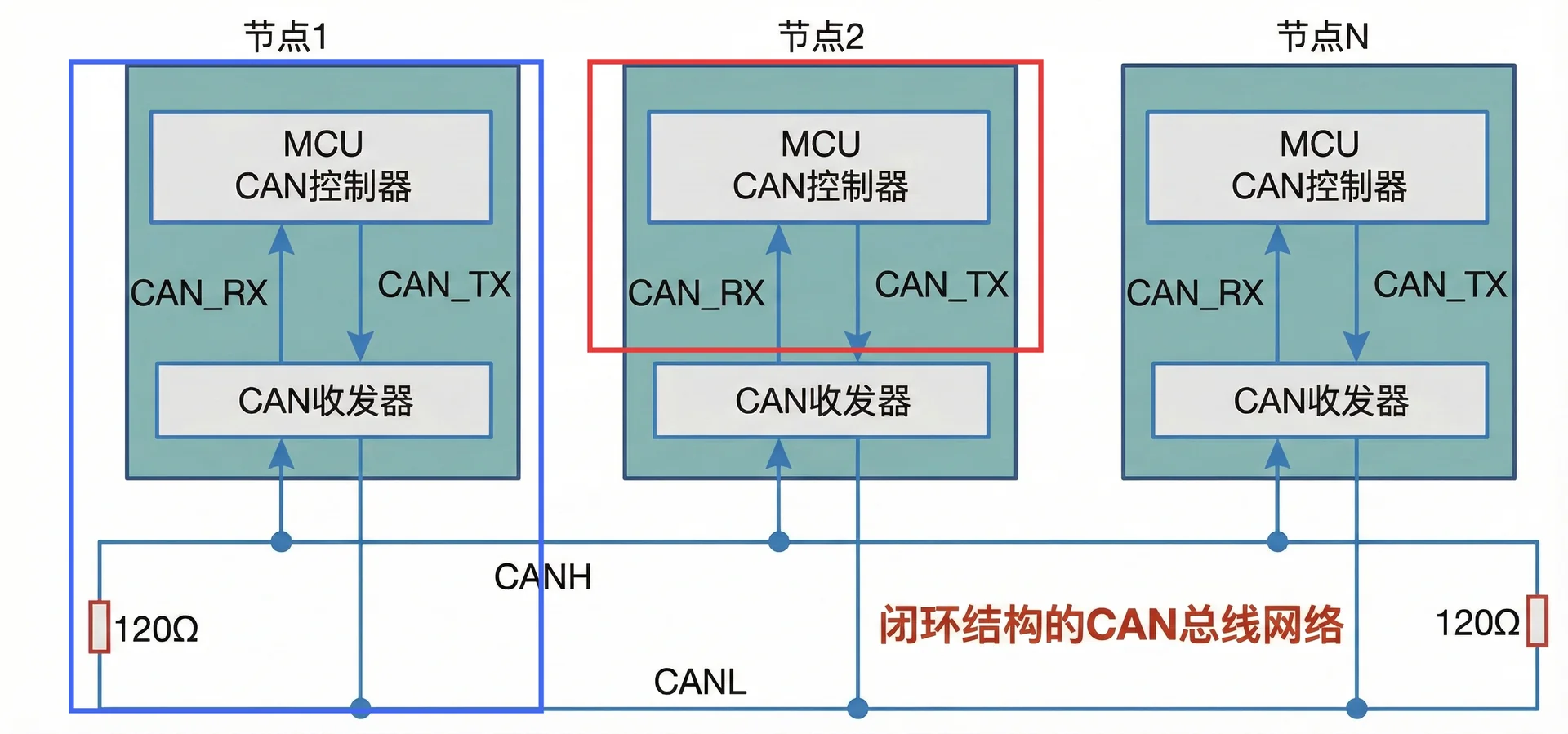
The C1901/C1902 has no CAN transceiver chip and only outputs the CAN_TX and CAN_RX signals.
The C2401 is equipped with a CAN transceiver chip. When communicating over the bus, set DIP switch 1 to ON to connect the 120Ω resistor; it outputs the CAN_H and CAN_L signals.
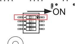
CAN Bus Configuration
- Load the relevant kernel modules
sudo modprobe can
sudo modprobe can_raw
sudo modprobe mttcan- Install the CAN utilities for sending and receiving
sudo apt-get install can-utils- Set the CAN0 baud rate to 10k
sudo ip link set down can0
sudo ip link set can0 type can bitrate 10000   # the interface must be brought down before each baud rate change
sudo ip link set up can0- Send data
cansend can0 123#00.00.00.00.11.11.11.11- Receive data
candump can0 &Check the CAN network status:
jetson@jetson-desktop:~$ ifconfig
can0: flags=193<UP,RUNNING,NOARP>  mtu 16
        unspec 00-00-00-00-00-00-00-00-00-00-00-00-00-00-00-00  txqueuelen 10  (UNSPEC)
        RX packets 2  bytes 16 (16.0 B)
        RX errors 0  dropped 0  overruns 0  frame 0
        TX packets 0  bytes 0 (0.0 B)
        TX errors 0  dropped 0 overruns 0  carrier 0  collisions 0
        device interrupt 110
At the protocol level, a CAN network has the following 3 states:
- Error Active - [Normal] This is the healthy state. The node can send and receive data normally; if it detects a bus error, it sends an "active error frame" (which disrupts the bus levels) to notify other nodes.
- Error Passive - [Warning] Entered when an error counter (RX/TX Error Counter) exceeds 127. The node can still send and receive data, but it transmits error frames passively to avoid disturbing the healthy nodes on the bus.
- Bus Off - [Critical] Entered when the transmit error counter exceeds 255. The CAN controller disconnects itself from the physical bus and completely stops sending and receiving data. Recovery requires restarting the interface (down then up) or configuring automatic restart (restart-ms).
5. RTC Interface
A real-time clock (RTC) is an independent timekeeping device that continues to provide accurate time and date information even when the system is powered off or the main power supply is shut down. The RTC is needed when the board runs in an offline environment and must keep time synchronized across power cycles.
The official kit does not support the RTC function.
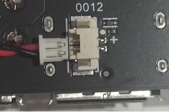
The RTC battery connector on the carrier board is MX1.25-2P. When using a battery, confirm the polarity carefully; connecting the battery in reverse is strictly prohibited.
- Check whether the system time is correct
timedatectl status- Synchronize the network time
sudo apt install ntpdate
sudo ntpdate cn.pool.ntp.org- Set the time zone
sudo timedatectl set-timezone Asia/Shanghai- Synchronize the system time to the RTC hardware
sudo hwclock --systohc --utc --rtc /dev/rtc0 --noadjfile- Check the RTC hardware time
sudo hwclock --show --utc --rtc /dev/rtc0 --noadjfile- Set up automatic RTC time synchronization at boot
- Open the file
sudo vi /lib/systemd/system/hwrtc.service- Write the following content
[Unit]
Description=Synchronise System clock to hardware RTC
DefaultDependencies=no
After=systemd-modules-load.service
Before=systemd-journald.service systemd-fsck-root.service time-sync.target sysinit.target shutdown.target
Conflicts=shutdown.target

[Service]
Type=oneshot
RemainAfterExit=yes
ExecStart=/sbin/hwclock --hctosys --utc --rtc /dev/rtc0 --noadjfile
RestrictRealtime=yes

[Install]
WantedBy=sysinit.target- Enable the service to start at boot
sudo systemctl enable hwrtc.service- Manually synchronize the RTC hardware time to the system
sudo hwclock --hctosys --utc --rtc /dev/rtc0 --noadjfile- Disable network time synchronization
sudo timedatectl set-ntp false