
C2401 Introduction
Overview
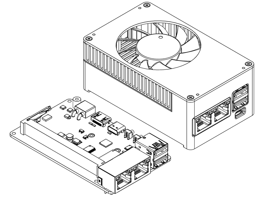
The C2401 is a high-density, compact carrier board developed for the Jetson Orin Nano and NX modules. Despite its small footprint it offers a complete set of interfaces — including dual Ethernet ports and dual USB ports — plus rich expansion capability such as 4G/5G module support.
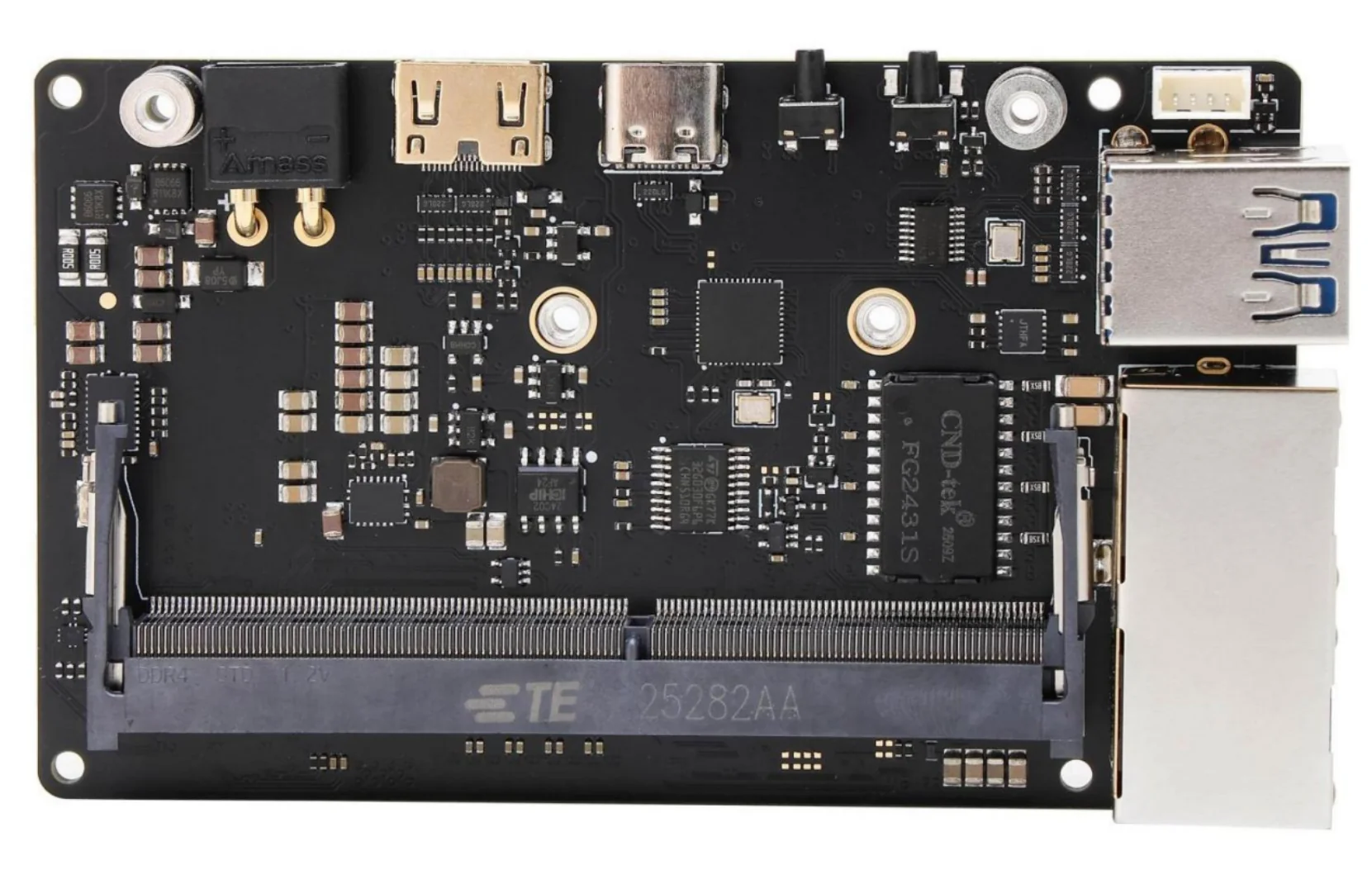
Front
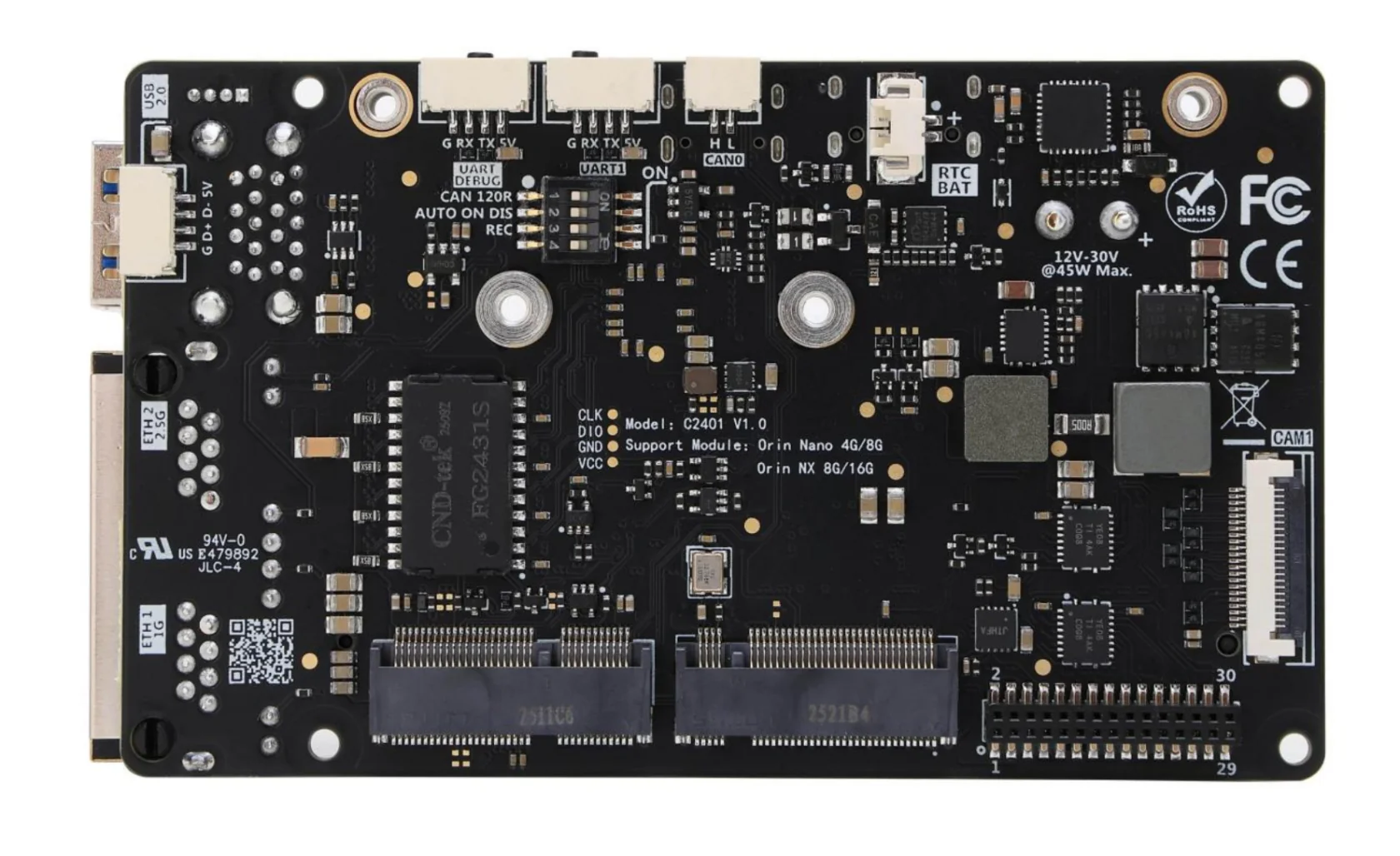
Back
Features
- Equipped with an advanced automotive-grade E-fuse chip: over-voltage, under-voltage, short-circuit, over-current and reverse-polarity protection
- Ultra-low-resistance Buck chip with alloy flat-wire inductor — low heat, high saturation current
- 8-layer, 2u immersion-gold via-in-pad PCB; external dimensions of only 55x92mm
- Dual USB 3.0 and dual Ethernet (one 2.5G port supports PTP + 16KB jumbo frames)
- Same-side M.2 layout — swap the Wi-Fi card / SSD without removing the module
Specifications
| Parameter | Value |
|---|---|
| Supply voltage | 12V compatible (9.5V–30V) |
| Power connector | XT30 interface |
| Supported modules | Orin Nano 4G/8G, Orin NX 8G/16G |
| Ethernet | 1x Gigabit (9KB jumbo frames) + 1x 2.5G (16KB jumbo frames, PTP) |
| Wireless | 1x M.2 Key E (2230) |
| Storage expansion | 1x M.2 Key M (2230 NVMe SSD) |
| Display | 1x Mini HDMI V2.1 |
| USB | 2x USB 3.2 (10 Gbps), 1x USB 2.0 (GH1.25-4p) |
| USB-C | 1x Type-C (USB 2.0), for firmware flashing |
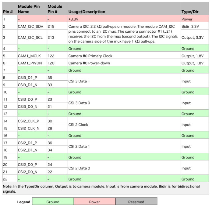
| Camera | 1x CSI-22P |
| Other interfaces | UART, CAN, I2C |
| RTC battery | 1x RTC backup-clock battery connector |
| Operating temperature | 0℃ ~ 45℃ |
Notes
- This board supports 12V (9.5V–30V) input; improve cooling when the voltage exceeds 15V.
- Reverse-polarity protection on the power input is provided.
- Each USB group outputs 2.5A max.
- Never insert or remove the module while the carrier board is powered.
Interface layout
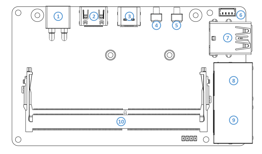
Front (#1-10)
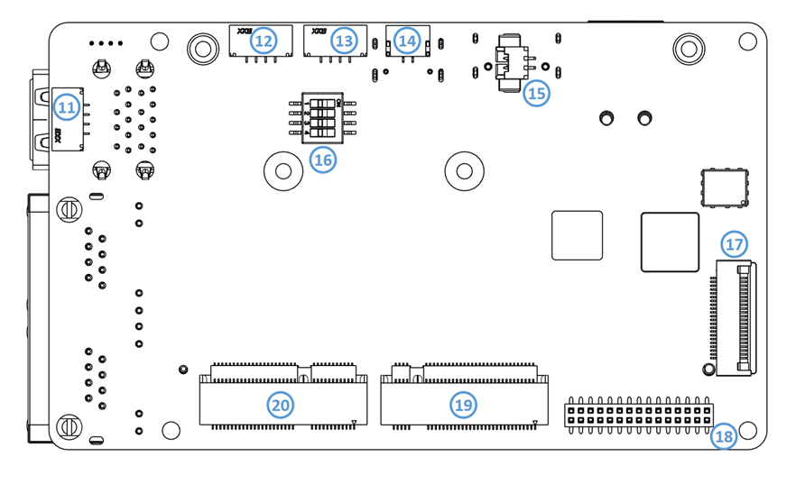
Back (#11-20)
| # | Name | # | Name |
|---|---|---|---|
| 1 | XT30 power connector | 11 | USB 2.0 connector (GH1.25 4p) |
| 2 | Mini HDMI port | 12 | UART DEBUG connector (GH1.25 4p) |
| 3 | USB Type-C (USB 2.0) | 13 | UART1 connector (GH1.25 4p) |
| 4 | REC button | 14 | CAN bus (GH1.25 2p) |
| 5 | Power button | 15 | RTC battery connector |
| 6 | PWM fan connector | 16 | 4-pin switch |
| 7 | USB 3.0 Type-A (2x stacked) | 17 | Camera (#1) 22-pin 0.5mm |
| 8 | RJ45 Ethernet 1 (2.5G) | 18 | 30-pin expansion socket |
| 9 | RJ45 Ethernet 2 (Gigabit) | 19 | M.2 M-key (2230) |
| 10 | Jetson Orin module socket (SO-DIMM) | 20 | M.2 E-key (2230) |
Selected functions and interfaces
Power connector (XT30)
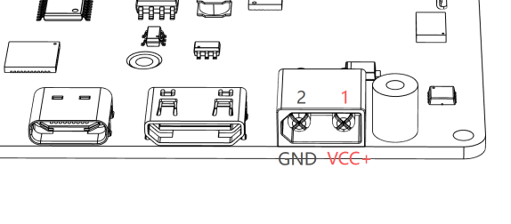
Recommended input voltage 12V, supports 10V–30V. Under-voltage protection at 9.5V, over-voltage protection at 31V.
| Module | Recommended power | USB-C PD requirement |
|---|---|---|
| Orin Nano 4G/8G | 45W | 20V 2.25A |
| Orin NX 8G/16G | 60W | 20V 3A |
REC button and boot
- Enter recovery mode: hold the REC button while powering on (recovery mode lasts about 60 seconds; the system boots normally if no connection is detected)
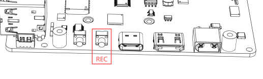
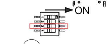
- Or set DIP switch 3 on the back to ON to auto-enter recovery mode on every power-up
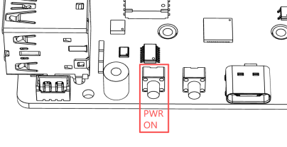
- Power button: when on, press once for the shutdown dialog / long-press 10s to force off; when off, press once to power on
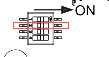
- Set DIP switch 2 on the back to ON to disable auto-power-on
Expansion socket (30-pin)
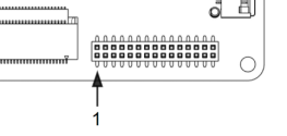
A 2x15-pin, 1.27mm-pitch female header. Pin 1 location and pinout:
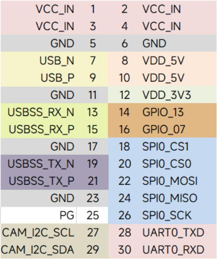
- VCC_IN passes the input voltage through, 3A max; VDD_5V / VDD_3V3 provide up to 1A each
- I2C, GPIO, SPI and UART pins are 3.3V logic
- PG signal: outputs high while the module is running normally
- USB 3.0 on pins 13/15/19/21 is disabled in the official firmware by default; see USB Configuration to enable it
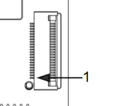
CSI camera port
USB, serial and CAN
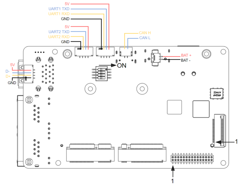
Wiring for USB 2.0, UART1, UART DEBUG, CAN and the RTC battery:
UART notes
- The
UART2 TXD/RXDlabels in the diagram refer to the UART DEBUG port. - UART1 is routed from M.2 Key E and requires the corresponding device tree to be replaced before it can be used.
RJ45 Ethernet
- Gigabit port (8): RTL8111 chip, no extra driver needed.
- 2.5G port (9): RTL8125 chip, requires an additional driver.
M.2 layout
The M.2 Key M and Key E slots are on the same (back) side — swap the Wi-Fi card / SSD without removing the module:
Dimensions
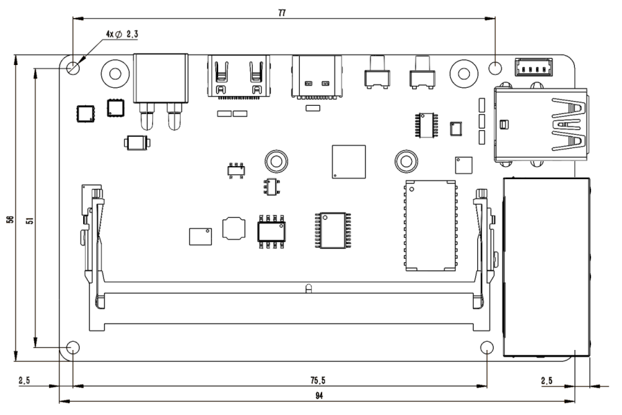
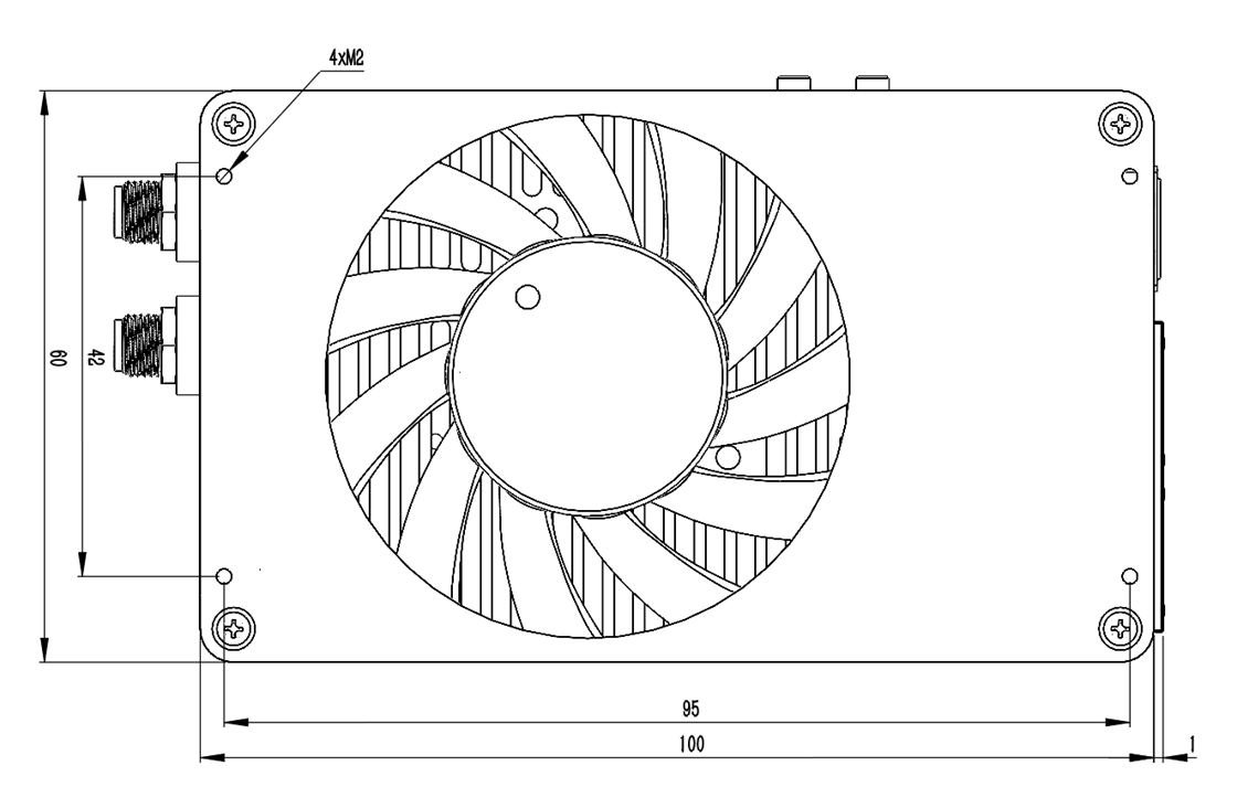
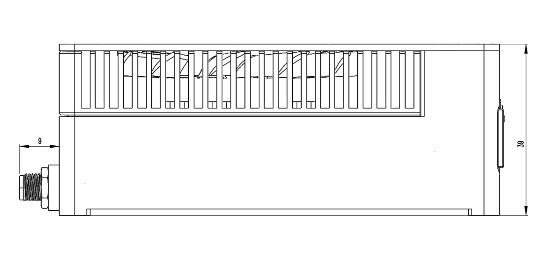
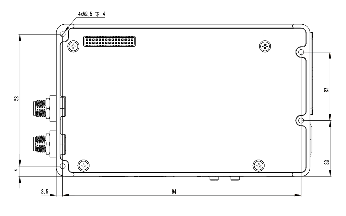
Board dimensions
| Location | Recommended screw | Notes |
|---|---|---|
| Board mounting holes | M2 screw or standoff | Max diameter ≤ 4.5mm |
| Module | M2.5 x 4 low-profile | Max diameter ≤ 5mm |
| M.2 connector | M2.5 x 4 low-profile | Max diameter ≤ 5mm |
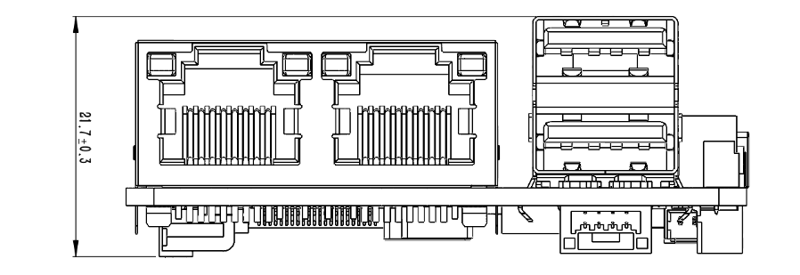
Side dimensions
More views
Technical support
- C2401 flashing guide
- Jetson getting-started tutorials
- JetPack configuration guides
- Jetson AI vision tutorials
- Jetson LLM tutorials
Source: LinkZee Labs — 控元科技(广州)有限公司