
C1902 Introduction
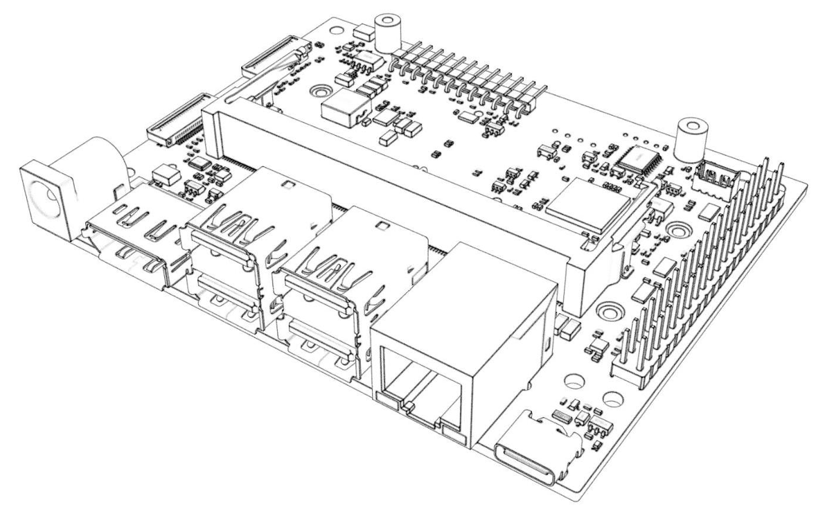
Overview
The C1902 is a carrier board developed for the Jetson Orin Nano & NX modules. Based on the reference design, it fully matches the features of the official developer kit, including full-speed USB 3.0 and Type-C ports.
Key features
- Developed from the original reference design — supports flashing the Developer Kit firmware directly
- Supports Orin Nano 4G/8G & Orin NX 8G/16G
- High-quality 6-layer immersion-gold PCB, all-MLCC capacitors and gold-plated connectors
- Supports NVMe SSD and M.2 Wi-Fi module
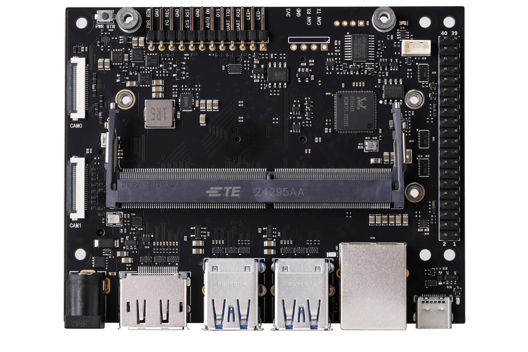
Front
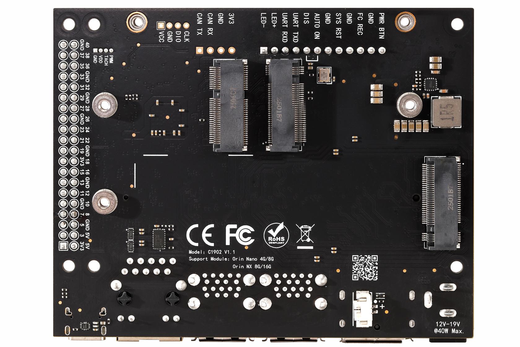
Back
Features
- The C1902 is developed from the original reference design; all interface functions match the original and it can flash the Developer Kit firmware directly.
- Supports Orin Nano 4G/8G & Orin NX 8G/16G.
- High-quality 6-layer immersion-gold PCB, all-MLCC capacitors and gold-plated connectors.
- Supports NVMe SSD and M.2 Wi-Fi module.
Revision history
| Version | Date | Notes |
|---|---|---|
| V1.0 | 2024 Q3 | First release of the C1902 |
| V1.1 | 2025 Q1 | 1. Fixed GPIO issue that made pins 12/35/38/40 unavailable 2. Added SUPER mode support across the whole series |
| V1.1.1 | 2025 Q2 | Changed the DC power jack from DC5521 to DC5525 |
Specifications
| Parameter | Value |
|---|---|
| Supply voltage | 12V (compatible with 9–19V) |
| Operating temperature | 0℃ ~ 45℃ |
| Supported modules | Orin Nano 4G/8G, Orin NX 8G/16G |
| Power connector | DC5525 |
| Ethernet | 1x Gigabit Ethernet (RJ45) |
| Wireless | 1x M.2 Key E |
| Storage expansion | 2x M.2 Key M (NVMe SSD) |
| Display | 1x DP 1.2 |
| USB | 4x USB 3.2 (10 Gbps) |
| USB-C | 1x Type-C (USB 3.0) |
| Camera | 2x CSI-2 22P |
| Other interfaces | Same as the original reference design |
| RTC battery | Supported |
| PoE | Not supported |
Notes
Important
- This board supports 12V (9V–19V) input; make sure the power supply provides sufficient wattage.
- Improve cooling when the voltage is above 15V under heavy load.
- Reverse-polarity protection is provided, but the power should never be connected in reverse.
- Each USB group is limited to 2.5A max, with automatic over-current cutoff.
- On the back, the Wi-Fi card and M.2 2230 layout are mirror-symmetric to the original design.
Prohibited
Never insert or remove the module while the carrier board is powered — doing so will cause damage, at your own risk.
Feature comparison
| Spec | Reference board | C1902 | C1901 |
|---|---|---|---|
| Supply voltage | 19V | 12V (9–19V) | 12V (9–19V) |
| Power connector | DC5525 | DC5525 | DC5521 |
| Ethernet | 1x Gigabit | 1x Gigabit | 1x Gigabit |
| Wireless | 1x M.2 Key E | 1x M.2 Key E | 1x M.2 Key E |
| Storage | 2x M.2 Key M | 2x M.2 Key M | 2x M.2 Key M |
| Display | 1x DP 1.2 | 1x DP 1.2 | 1x HDMI (1080P) |
| USB | 4x USB 3.0 | 4x USB 3.0 | 3x USB 3.0 + 1x USB 2.0 |
| USB-C | 1x Type-C (3.0) | 1x Type-C (3.0) | 1x Type-C (2.0) |
| Camera | 2x CSI-2 | 2x CSI-2 | 2x CSI-2 |
| RTC | Not supported | ✅ Supported | ✅ Supported |
| PoE | Supported (unpopulated) | ❌ | ❌ |
| SUPER mode | Nano only | ✅ Whole series | Nano only |
Interface layout
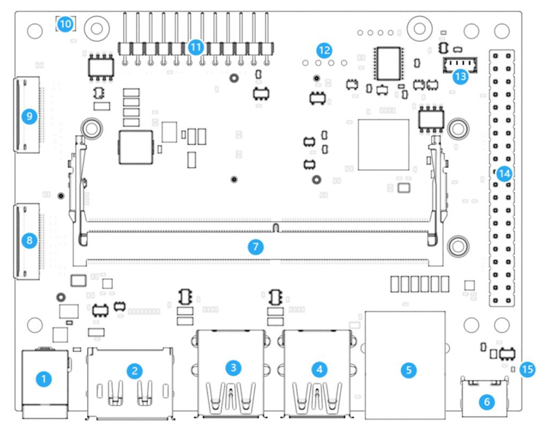
Front
| # | Name | Notes |
|---|---|---|
| 1 | Power input | DC5525 |
| 2 | DP port | DP 1.2 |
| 3-4 | USB Type-A | 4x USB 3.0 |
| 5 | Ethernet | Gigabit RJ45 |
| 6 | USB Type-C | Firmware flashing |
| 7 | SO-DIMM | 260-pin, Jetson module |
| 8 | 40-pin GPIO | I2C/SPI/UART/GPIO |
| 9-10 | CSI port | 22P-CSI |
| 11 | Power button | Short press power on/off, long press force off |
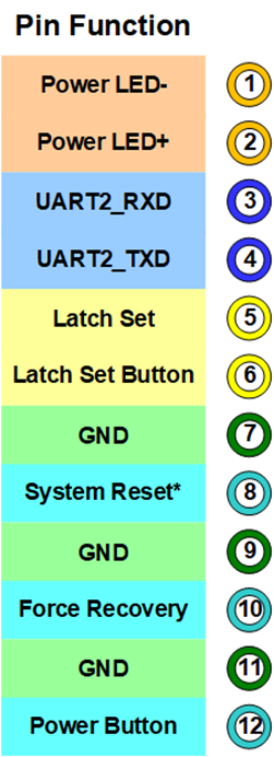
| 12 | 12-pin debug | - |
| 13 | CAN | Unpopulated |
| 14 | Fan | PWM speed control |
| 15 | 40-pin expansion | - |
Back
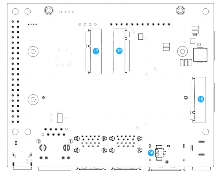
| # | Name | Notes |
|---|---|---|
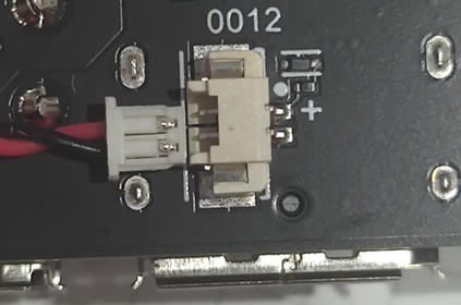
| 16 | RTC battery | MX1.25-2P, 3V |
| 17 | M.2 Key M | 2230 (2-lane) |
| 18 | M.2 Key M | 2280 (4-lane) |
| 19 | M.2 Key E | 2230 |
Selected function notes
Power button
- When the system is running: short press to open the shutdown dialog, long press 10s to force off.
- When the system is off: short press to power on.
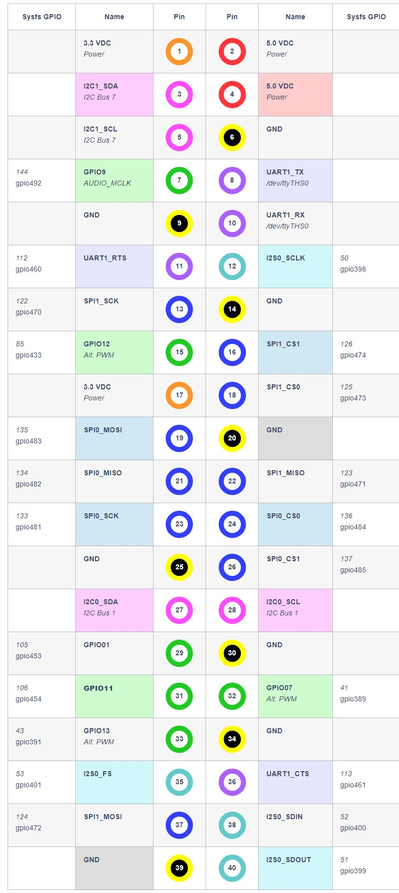
40-pin header
The 5V output on the 40-pin GPIO has back-feed protection, 0.8A max, with over-current cutoff.
12-pin debug port
RTC battery
MX1.25-2P connector, battery voltage 3V. Mind the polarity — never connect in reverse.
TIP
The RTC clock must be configured after connecting the battery before it is enabled.
SSD note
The SSD must be a single-sided version; double-sided drives may interfere and short out.
Dimensions (mm)
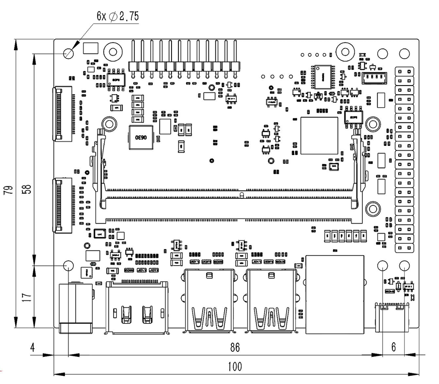
| Screw location | Recommended spec | Notes |
|---|---|---|
| Board mounting holes | M2.5 screw or standoff | Diameter ≤ 6mm |
| Module / SSD | M2.5 x 4 low-profile screw | - |
| Wi-Fi card | M2.5 x 4 low-profile screw | - |
Source: LinkZee Labs — 控元科技(广州)有限公司